- 您现在的位置:买卖IC网 > Sheet目录3890 > PIC16C774T-E/L (Microchip Technology)IC MCU OTP 4KX14 A/D PWM 44PLCC
1999 Microchip Technology Inc.
Advance Information
DS30275A-page 1
Microcontroller Core Features:
High-performance RISC CPU
Only 35 single word instructions to learn
All single cycle instructions except for program
branches which are two cycle
Operating speed: DC - 20 MHz clock input
DC - 200 ns instruction cycle
4K x 14 words of Program Memory,
256 x 8 bytes of Data Memory (RAM)
Interrupt capability (up to 14 internal/external
interrupt sources)
Eight level deep hardware stack
Direct, indirect, and relative addressing modes
Power-on Reset (POR)
Power-up Timer (PWRT) and
Oscillator Start-up Timer (OST)
Watchdog Timer (WDT) with its own on-chip RC
oscillator for reliable operation
Programmable code-protection
Power saving SLEEP mode
Selectable oscillator options
Low-power, high-speed CMOS EPROM
technology
Fully static design
In-Circuit Serial Programming
(ISCP)
Wide operating voltage range: 2.5V to 5.5V
High Sink/Source Current 25/25 mA
Commercial and Industrial temperature ranges
Low-power consumption:
- < 2 mA @ 5V, 4 MHz
- 22.5
A typical @ 3V, 32 kHz
-< 1
A typical standby current
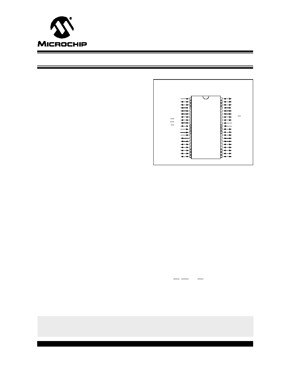
Pin Diagram
Peripheral Features:
Timer0: 8-bit timer/counter with 8-bit prescaler
Timer1: 16-bit timer/counter with prescaler,
can be incremented during sleep via external
crystal/clock
Timer2: 8-bit timer/counter with 8-bit period
register, prescaler and postscaler
Two Capture, Compare, PWM modules
Capture is 16-bit, max. resolution is 12.5 ns,
Compare is 16-bit, max. resolution is 200 ns,
PWM max. resolution is 10-bit
12-bit multi-channel Analog-to-Digital converter
On-chip absolute bandgap voltage reference
generator
Synchronous Serial Port (SSP) with SPI (Master
Mode) and I2C
Universal Synchronous Asynchronous Receiver
Transmitter, supports high/low speeds and 9-bit
address mode (USART/SCI)
Parallel Slave Port (PSP) 8-bits wide, with
external RD, WR and CS controls
Programmable Brown-out detection circuitry for
Brown-out Reset (BOR)
Programmable Low-voltage detection circuitry
600 mil. PDIP, Windowed CERDIP
RB7
RB6
RB5
RB4
RB3/AN9/LVDIN
RB2/AN8
RB1/SS
RB0/INT
VDD
VSS
RD7/PSP7
RD6/PSP6
RD5/PSP5
RD4/PSP4
RC7/RX/DT
RC6/TX/CK
RC5/SDO
RC4/SDI/SDA
RD3/PSP3
RD2/PSP2
MCLR/VPP
RA0/AN0
RA1/AN1
RA2/AN2/VREF-/VRL
RA3/AN3/VREF+/VRH
RA4/T0CKI
RA5/AN4
RE0/RD/AN5
RE1/WR/AN6
RE2/CS/AN7
AVDD
AVSS
OSC1/CLKIN
OSC2/CLKOUT
RC0/T1OSO/T1CKI
RC1/T1OSI/CCP2
RC2/CCP1
RC3/SCK/SCL
RD0/PSP0
RD1/PSP1
1
2
3
4
5
6
7
8
9
10
11
12
13
14
15
16
17
18
19
20
40
39
38
37
36
35
34
33
32
31
30
29
28
27
26
25
24
23
22
21
PIC1
6C77
4
*
PIC16C77X
28/40-Pin, 8-Bit CMOS Microcontrollers w/ 12-Bit A/D
* Enhanced features
This is an advanced copy of the data sheet and therefore the contents and
specifications are subject to change based on device characterization.
发布紧急采购,3分钟左右您将得到回复。
相关PDF资料
PIC16F74T-E/L
IC MCU FLASH 4KX14 A/D 44PLCC
PIC16C765T-I/L
IC MCU OTP 8KX14 USB 44PLCC
PIC18C442T-E/L
IC MCU OTP 8KX16 A/D 44PLCC
PIC16C621A-40/SS
IC MCU OTP 1KX14 COMP 20SSOP
PIC16C622A-40/SS
IC MCU OTP 2KX14 COMP 20SSOP
PIC16CE623-30/SO
IC MCU OTP 512X14 EE COMP 18SOIC
PIC16CE624-30/SO
IC MCU OTP 1KX14 EE COMP 18SOIC
PIC16CE624-30/SS
IC MCU OTP 1KX14 EE COMP 20SSOP
相关代理商/技术参数
PIC16C774T-E/PQ
功能描述:8位微控制器 -MCU 7KB 256 RAM 33 I/O RoHS:否 制造商:Silicon Labs 核心:8051 处理器系列:C8051F39x 数据总线宽度:8 bit 最大时钟频率:50 MHz 程序存储器大小:16 KB 数据 RAM 大小:1 KB 片上 ADC:Yes 工作电源电压:1.8 V to 3.6 V 工作温度范围:- 40 C to + 105 C 封装 / 箱体:QFN-20 安装风格:SMD/SMT
PIC16C774T-E/PT
功能描述:8位微控制器 -MCU 7KB 256 RAM 33 I/O RoHS:否 制造商:Silicon Labs 核心:8051 处理器系列:C8051F39x 数据总线宽度:8 bit 最大时钟频率:50 MHz 程序存储器大小:16 KB 数据 RAM 大小:1 KB 片上 ADC:Yes 工作电源电压:1.8 V to 3.6 V 工作温度范围:- 40 C to + 105 C 封装 / 箱体:QFN-20 安装风格:SMD/SMT
PIC16C774T-I/L
功能描述:8位微控制器 -MCU 7KB 256 RAM 33 I/O RoHS:否 制造商:Silicon Labs 核心:8051 处理器系列:C8051F39x 数据总线宽度:8 bit 最大时钟频率:50 MHz 程序存储器大小:16 KB 数据 RAM 大小:1 KB 片上 ADC:Yes 工作电源电压:1.8 V to 3.6 V 工作温度范围:- 40 C to + 105 C 封装 / 箱体:QFN-20 安装风格:SMD/SMT
PIC16C774T-I/PQ
功能描述:8位微控制器 -MCU 7KB 256 RAM 33 I/O RoHS:否 制造商:Silicon Labs 核心:8051 处理器系列:C8051F39x 数据总线宽度:8 bit 最大时钟频率:50 MHz 程序存储器大小:16 KB 数据 RAM 大小:1 KB 片上 ADC:Yes 工作电源电压:1.8 V to 3.6 V 工作温度范围:- 40 C to + 105 C 封装 / 箱体:QFN-20 安装风格:SMD/SMT
PIC16C774T-I/PT
功能描述:8位微控制器 -MCU 7KB 256 RAM 33 I/O RoHS:否 制造商:Silicon Labs 核心:8051 处理器系列:C8051F39x 数据总线宽度:8 bit 最大时钟频率:50 MHz 程序存储器大小:16 KB 数据 RAM 大小:1 KB 片上 ADC:Yes 工作电源电压:1.8 V to 3.6 V 工作温度范围:- 40 C to + 105 C 封装 / 箱体:QFN-20 安装风格:SMD/SMT
PIC16C77T-04/L
功能描述:8位微控制器 -MCU 14KB 368 RAM 33 I/O RoHS:否 制造商:Silicon Labs 核心:8051 处理器系列:C8051F39x 数据总线宽度:8 bit 最大时钟频率:50 MHz 程序存储器大小:16 KB 数据 RAM 大小:1 KB 片上 ADC:Yes 工作电源电压:1.8 V to 3.6 V 工作温度范围:- 40 C to + 105 C 封装 / 箱体:QFN-20 安装风格:SMD/SMT
PIC16C77T-04/PQ
功能描述:8位微控制器 -MCU 14KB 368 RAM 33 I/O RoHS:否 制造商:Silicon Labs 核心:8051 处理器系列:C8051F39x 数据总线宽度:8 bit 最大时钟频率:50 MHz 程序存储器大小:16 KB 数据 RAM 大小:1 KB 片上 ADC:Yes 工作电源电压:1.8 V to 3.6 V 工作温度范围:- 40 C to + 105 C 封装 / 箱体:QFN-20 安装风格:SMD/SMT
PIC16C77T-04/PT
功能描述:8位微控制器 -MCU 14KB 368 RAM 33 I/O RoHS:否 制造商:Silicon Labs 核心:8051 处理器系列:C8051F39x 数据总线宽度:8 bit 最大时钟频率:50 MHz 程序存储器大小:16 KB 数据 RAM 大小:1 KB 片上 ADC:Yes 工作电源电压:1.8 V to 3.6 V 工作温度范围:- 40 C to + 105 C 封装 / 箱体:QFN-20 安装风格:SMD/SMT